Next: Comparisons with Other Models
Up: Model Description
Previous: Spherical Correction
Refraction
In constructing the mathematical model to describe the transfer
of radiation in Earth's atmosphere, one potentially important effect
has been neglected: refraction. As light passes between mediums
possessing different optical properties, it is refracted or bent.
Refraction has been shown to be
important for both occultation (Smith and Hunten, 1990) and in the
calculation of J-values
near sunset (DeMajistre et al., 1995; Balluch and Lary, 1997) and
so its effect on limb radiances is likely to be important.
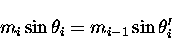
The relationship between initial and refracted zenith angles
is given by Snell's law,
 |
(7.47) |
where the mi is the refractive index of an atmospheric layer between
zi and zi+1,  is the incident zenith angle
and
is the incident zenith angle
and  is the refracted zenith angle.
Snell's law can be derived from the Fresnel equations
(e.g.: Jackson, 1960).
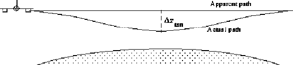
For light propagating through Earth's atmosphere and passing from
lower density to higher density air, by Snell's law, the path the
light traverses will be bent towards the surface. As the density
of the air is continually changing, light is continually being
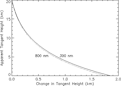
refracted. This effect is shown schematically for the ER-2 in Figure 4.4.
is the refracted zenith angle.
Snell's law can be derived from the Fresnel equations
(e.g.: Jackson, 1960).
For light propagating through Earth's atmosphere and passing from
lower density to higher density air, by Snell's law, the path the
light traverses will be bent towards the surface. As the density
of the air is continually changing, light is continually being
refracted. This effect is shown schematically for the ER-2 in Figure 4.4.
Figure 4.4:
The difference between apparent and actual paths through the
limb of the atmosphere as a result of refraction.
 |
The continuous nature of atmospheric refraction makes implementing
it in radiative transfer models difficult and
no attempt will be made to do so here. Instead, a
correction term will be utilized which will shift the elevation
angle of the limb radiance (and derived quantities) to one which
is more representative of the atmospheric region sensed.
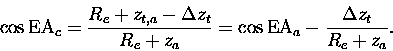
Figure 4.5:
The refraction of light at discrete layers and its impact on
tangent height.
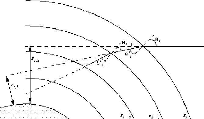 |
The effects of refraction can be quantified using Snell's law and
trigonometry and an expression which describes the change in tangent
height due to refraction can be derived.
Consider a pencil of light at height zi, making an angle
with the local surface normal, and propagating downward
with initial tangent height zt,i. Upon refraction, it
has a local zenith angle of ,
as shown in Figure 4.5 .
At the next layer interface, zi-1, the local zenith angle is
 .
They can be related using the law of sines,
.
They can be related using the law of sines,
 |
(7.48) |
and upon substitution of Snell's law,
 |
(7.49) |
the local zenith at zi-1 can be expressed in terms of the
local zenith angle at zi. Carrying out one more
iteration,
 |
(7.50) |
and upon canceling rearranging,
 |
(7.51) |
the pattern becomes clear. Using the definition for tangent height,
 |
(7.52) |
and generalizing the result,
 |
(7.53) |
an expression relating the tangent height of the refracted pencil
at height zj to the apparent (unrefracted) tangent height is
arrived at. This is called the formula of Bouguer
which can also be arrived by considering how the optical path
behaves in a medium with spherical symmetry (Born and Wolf, 1975).
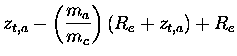
The change in tangent height as a result of refraction is,
where zt,a is the apparent tangent height as seen by
the CPFM and zt,c is the actual, or corrected, tangent height.
The refractive indices are calculated at the altitude of the
ER-2, ma, and the altitude of the corrected tangent height,
mc. As the corrected tangent height is an unknown, mc will
be initially evaluated at the apparent tangent height, and upon
calculating
 ,
a second iteration can be performed
evaluating mc at
,
a second iteration can be performed
evaluating mc at
 .
.
An expression for refractive index of air (or any ideal gas) can be derived by
considering the molecules comprising air to be simple dipoles under
the influence of an
electric field. This treatment yields the general result,
 |
(7.55) |
where N is the number density,  a resonance wavelength
(in general, there will be many resonance wavelengths),
and k a constant.
The dispersive term can be expanded in a Laurent series and for air from the
near-UV to the near-IR, only the
a resonance wavelength
(in general, there will be many resonance wavelengths),
and k a constant.
The dispersive term can be expanded in a Laurent series and for air from the
near-UV to the near-IR, only the
 term will be important.
Using,
term will be important.
Using,
 ,
Cauchy's formula is arrived at (Born and Wolf, 1959),
,
Cauchy's formula is arrived at (Born and Wolf, 1959),
 |
(7.56) |
where
 and
and
 m2 at
surface pressure.
If B is taken as pressure independent and utilizing the fact that
m2 at
surface pressure.
If B is taken as pressure independent and utilizing the fact that
 ,
the refractive index at any height can
be obtained by multiplying the left hand side of equation (4.56)
by e-z/H, where H is some suitable scale height obtained by
assuming an isothermal atmosphere.
This allows equation (4.54) to be written as,
,
the refractive index at any height can
be obtained by multiplying the left hand side of equation (4.56)
by e-z/H, where H is some suitable scale height obtained by
assuming an isothermal atmosphere.
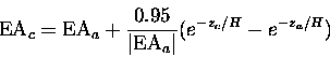
This allows equation (4.54) to be written as,
 |
(7.57) |
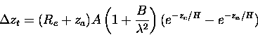
where ReA=1.84 km which roughly represents the maximum change in
tangent height resulting from refraction.
Equation (4.57) has been plotted for wavelengths of
300 nm and 800 nm in Figure 4.6 for the ER-2 at 20 km. Note that
for a satellite, the equation is nearly identical except that
za is replaced with the orbital altitude.
For ODIN, as an example, za=600 km which would increase the
values of
from Figure 4.6 by about 17%.
Figure 4.6:
Effect of refraction on tangent height as determined
using equation (4.57) for the ER-2 at 20 km.
 |
Clearly, from Figure 4.6, refraction can become important for tangent
heights near the surface. If the corrected tangent height is
then the corrected elevation angle, EAc, is
given by,
 |
(7.58) |
where EAa is the CPFM apparent elevation angle.
For
 ,
a small argument
expansion for cosine (
,
a small argument
expansion for cosine (
 )
may be used,
)
may be used,
 |
(7.59) |
and using
 ,
the corrected
elevation angle is,
,
the corrected
elevation angle is,
 |
(7.60) |
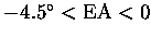
Note the correction term is proportional to (EAa)-1 which means
for larger elevation angles, the effects of refraction decrease
(although for EA
 ,
the small argument expansion cannot
be used).
Also, for EA
,
the small argument expansion cannot
be used).
Also, for EA
 ,
,
 ,
so that
the correction term goes to zero.
Further, using zc assumes that the majority of the signal is originating
at the tangent point which, depending primarily on wavelength, may not be
the case. As will be discussed further in Chapter 5, most of the
information reaching the instrument is from light scattering
into the line of sight before the slant optical depth,
,
so that
the correction term goes to zero.
Further, using zc assumes that the majority of the signal is originating
at the tangent point which, depending primarily on wavelength, may not be
the case. As will be discussed further in Chapter 5, most of the
information reaching the instrument is from light scattering
into the line of sight before the slant optical depth,  ,
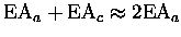
reaches unity. At 500 nm, equation (4.60) becomes,
,
reaches unity. At 500 nm, equation (4.60) becomes,
 |
(7.61) |
where EAa and EAc are in degrees.
The corrections, which will decrease the elevation angle, will be
applied to the elevation angle of the measurements.
The three different cases are:
- 1.
-
 :
No corrections as refraction effects small
above 20 km
:
No corrections as refraction effects small
above 20 km
- 2.
-
 :
Equation (4.60) used with
zc taken as altitude at which slant optical depth equals unity
(if
:
Equation (4.60) used with
zc taken as altitude at which slant optical depth equals unity
(if  is reached above zt,c) or zt,c (otherwise).
- 3.
-
 :
Equation (4.60) used with
zc taken as altitude at which slant optical depth equals unity
(if
is reached above 0 km) or 0 km (otherwise).
:
Equation (4.60) used with
zc taken as altitude at which slant optical depth equals unity
(if
is reached above 0 km) or 0 km (otherwise).
Equation (4.61)
predicts a maximum change of about 0.2 near an elevation
angle of
near an elevation
angle of
 .
.
Next: Comparisons with Other Models
Up: Model Description
Previous: Spherical Correction
Chris McLinden
1999-07-22